Building an x86 "Motherboard" by Gen AI and Running MS-DOS on It
日本語版もあります。
Motivation
One of my hobbies is building PCs. At some point, someone asked me, “Have you ever built a motherboard yourself?” That made me realize that, no, I actually hadn’t — and that sounded like something worth trying.
I have many friends who build microcontroller boards (like Arduino style dev board), but if you’re going to call it a motherboard, it should have a swappable CPU. And if you’re going to call it a “PC” (not just a computer), then it should really use an x86 CPU rather than something like ARM.

In fact, a few years ago I managed to get my hands on an 8088 CPU and tried this once before, but it didn’t go very well.
This time, I decided to try again, incorporating what I learned last time.
-
Use a V30 instead of an 8086 The 8086 uses a process called HMOS, which is essentially an NMOS-based process, and it doesn’t play well with CMOS ICs. CMOS reduces power consumption by arranging NPN and PNP transistors symmetrically, but older HMOS (Intel’s NMOS process) uses only NPN transistors and consumes a lot more current. When a signal is driven from a CMOS chip into an NMOS chip, the current demand can be so high that the CMOS chip can’t drive it properly. Come to think of it, this is where things like fan-out and fan-in come into play — something I vaguely remember learning long ago. This time, I decided to use the V30, which is a 8086 clone fabricated using a CMOS process.
-
Generate the clock at a constant interval and at a reasonably high speed In my previous attempt, I assumed the CPU would run no matter how slow the clock was, and even if the clock wasn’t periodic. I would stop the clock in the middle of execution to print debug output. However, after talking to people who actually know what they’re doing, I learned that there are constraints on the clock. In particular, with NMOS-based CPUs, letting the interval between clock edges get too long can cause problems. This time, I used hardware PWM to generate a clock with a constant interval, and I tried to make it as fast as reasonably possible.
-
Use generative AI Carefully reading datasheets, designing circuits, and writing control software is hard. This time, I leaned on generative AI to help design both the hardware and the control software.
Hardware Configuration and Design

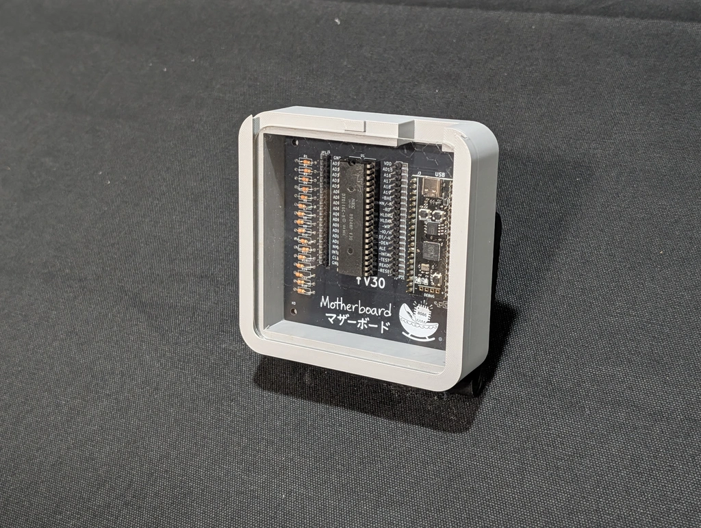
For the main CPU, I used a V30 (part number μPD70116). The V30 is an 8086-compatible CPU made by NEC, used in old PC-98 machines. I used one myself when I was in elementary school. I bought them on AliExpress for about $2 each.
As mentioned earlier, this CPU is fabricated using a CMOS process, so it’s more tolerant of longer clock intervals than NMOS CPUs. The clock itself is generated using a PWM generator to ensure a constant period.
In my previous attempt, I also struggled with voltage levels. CPUs from that era operate at 5 V, while modern circuits usually run at 3.3 V or lower. Last time, I tried to solve this with level shifters, but it didn’t work out well. After researching again, I found many reports claiming that this 5 V CPU can actually run at 3.3 V (for example: https://github.com/dbalsom/arduinoX86). If the entire circuit runs at 3.3 V, voltage level issues disappear. Although 3.3 V is outside the guaranteed range in the V30 datasheet, I figured that if it works, it’s a win — and decided to try it.
Normally, system glue logic like this would be implemented with special ICs, logic ICs or ASIC, but this time I took a shortcut and used an RP2040. In other words, this project uses a real V30 CPU, but everything else is implemented on the RP2040. I call this RP2040 side the “cradle”
I decided on the circuit design by consulting Gemini. I asked it which components should connect to which, had it output the result as a table (essentially a netlist), and then manually transcribed that into KiCad. It would probably be possible to generate a script or a netlist file directly, but I didn’t go that far.
Component placement and board size were specified manually, without AI. The board is a 10 cm x 10 cm square — the largest size eligible for coupons — and components were placed with plenty of spacing. When I do this kind of work, I usually write Python scripts and use the KiCad API, so that it’s easy to redo everything if I need to redesign the circuit. Writing such scripts is probably something AI could handle fairly easily.
The conversion from netlist to physical wiring was done using Freerouting’s autorouter.
As a bonus, I used Nano banana to generate a project logo and hand-written-style “motherboard” text, which I placed in the silkscreen area.


Software Architecture
There is software that runs on the V30 itself, and software that runs on the cradle side.
These were also written with the help of AI, using a kind of “vibe coding.”
I launched gemini-cli in an empty directory and just started asking for things.
The cradle-side control software was written in C++ using the Pico SDK.
For example, the cradle monitors when the CPU tries to read memory, fetches data from its own memory, and passes it to the CPU.
Bus control timing is very tight, but I also use a USB-CDC console for debugging. Handling USB interrupts interferes with timing and causes failures.
When I asked the AI about this, it suggested using the RP2040’s second core. One core handles communication with the PC, while the other focuses exclusively on controlling the V30.
The AI recommended using the RP2040’s inter-core synchronization queues,
but I wondered whether simple global variables with volatile wouldn’t be enough.
Still, I decided not to interfere — this project is driven by a “if it works, it works” vibe.
The AI also suggested using PIO for faster bus control, but that would make the code unreadable for me, so for now everything is written in C++.
Out of the RP2040’s 264 KB of RAM, 128 KB is allocated to the V30. All memory accesses from the V30 are served from this region.
Memory accesses are also logged, and the log can be displayed on request from the PC.
Since I was at it, I asked the AI to write an assembler and a disassembler. It generated both the parser and the machine code generator in C. This kind of work — complex enough to be annoying, but mostly just a lot of code — is probably a good fit for AI.
Overall, the system acts like a monitor program that can be controlled from a terminal. The following commands are implemented:
d <addr> [len] : Dump memory
e <addr> <val> : Edit memory
f [val]        : Fill memory with byte (default F4)
a <addr>       : Assemble interactively
l <addr> [len] : Disassemble
r [cycles]     : Run & Log for specified cycles (0 or omit for infinite)
i [cycles]     : Run & Log IO only for specified cycles (0 or omit for infinite)
g              : Run Loop (Key stop)
c <kHz>        : Set V30 clock speed
xr/xs          : XMODEM Recv/Send RAM
xl             : XMODEM Send Log
v              : Version
autotest [io]  : Full auto test (Rx -> Run -> Tx Log)
b              : Reboot to BOOTSEL mode
Debugging
Once everything was supposedly complete, I sent the PCB design to a professional manufacturer.
After soldering the finished board and flashing the firmware, nothing worked at all.
When I told the AI about this, it suggested changing the circuit and trying again.
I don’t think the AI understands the cost and effort involved in ordering boards from overseas and soldering them by hand. This is what I mean when I say AI lacks physicality. Some people claim that 2026 will be the year of “physical AI,” but unless AI truly understands real-world costs, that seems unlikely.
So I debugged it manually. I connected a logic analyzer I had at home, but as soon as I powered up the CPU, the logic analyzer went berserk.
After about half a day of trial and error, I realized it was a timing issue.
The V30 (and 8086) share address and data lines, switching their roles based on timing. When an RD signal indicates a memory read, the bus direction changes on the next clock. However, in the AI-generated code, data was driven immediately when RD was asserted. As a result, signals collided and shorted.
Because the “motherboard” was connected via USB, the host PC cut USB power for protection, and the logic analyzer — also connected via USB — was disconnected as collateral damage.
This should have been obvious from the timing charts in the datasheet (scanned PDFs written in the 1980s), but perhaps AI still struggles to read diagrams.
Maybe it’s a bad idea to let AI control anything that can short a power supply.
I added a small delay after RD before continuing, and simple operations like addition started working correctly.
When I tried more complex cases, I discovered that executing instructions located at odd addresses caused runaway behavior.
After investigating, I found another bug. On the 8086, odd and even address bytes are stored in separate memory chips, and the BHE signal selects which chip is used. The AI apparently didn’t understand this well and handled it incorrectly.
After fixing this by hand, things started working properly.
Run hand assembled code
mon> e 100 B8
Updated.
mon> e 101 01
Updated.
mon> e 102 00
Updated.
mon> e 103 A3
Updated.
mon> e 104 00
Updated.
mon> e 105 02
Updated.
mon> e 106 f4
Updated.
mon> a FFFF0 EA
FFFF0: .
mon> e FFFF0 EA
Updated.
mon> e FFFF1 00
Updated.
mon> e FFFF2 01
Updated.
mon> e FFFF3 00
Updated.
mon> e FFFF4 00
Updated.
mon> e FFFF5 00
Updated.
mon> r
Running V30 (Logging, Infinite cycles). Press any key to stop...
--- Log (10 bus cycles executed, 101474 us) ---
ADDR  |B|TY|DATA
FFFF0|B|RD|00EA
FFFF2|B|RD|0001
FFFF4|B|RD|0000
FFFF6|B|RD|F4F4
00100|B|RD|01B8
00102|B|RD|A300
00104|B|RD|0200
00106|B|RD|F4F4
00200|B|WR|0001
00108|B|RD|F4F4
Run a code assembled by AI generated assembler
mon> a 100
00100: mov ax, 1 -> B8 01 00
00103: mov bx, 2 -> BB 02 00
00106: add ax, bx -> 01 D8
00108: mov [200], ax -> A3 00 02
0010B: db f4 -> F4
0010C: .
mon> a FFFF0
FFFF0: jmp far 0000:0100 -> EA 00 01 00 00
FFFF5: .
mon> r
Running V30 (Logging, Infinite cycles). Press any key to stop...
--- Log (13 bus cycles executed, 101537 us) ---
ADDR  |B|TY|DATA
FFFF0|B|RD|00EA
FFFF2|B|RD|0001
FFFF4|B|RD|F400
FFFF6|B|RD|F4F4
00100|B|RD|01B8
00102|B|RD|BB00
00104|B|RD|0002
00106|B|RD|D801
00108|B|RD|00A3
0010A|B|RD|F402
0010C|B|RD|F4F4
00200|B|WR|0003
0010E|B|RD|F4F4
mon>
Run a code assembled by GAS
; V30 (8086) Test Program for Pico Monitor
; Calculates 1+2 and stores the result '3' at address 0x0100.
cpu 8086        ; Specify 8086 mode
org 0           ; Assume code is loaded at address 0

; ==========================================
;  Main Program (at 0x0000)
; ==========================================
start:
    mov al, 1       ; Load 1 into AL register
    add al, 2       ; Add 2 to AL (result is 3)

    mov [0x0100], al ; Write the result to memory address 0x0100
                     ; This will appear in the bus log as a WR cycle.
    out 5, al      ; Output the result to IO port 5

    hlt             ; Halt the CPU. The Pico will detect this via timeout.

; ==========================================
;  Padding up to the reset vector
; ==========================================
; Fill the space from the current address ($) up to just before
; the reset vector (0x1FFF0) with NOP (0x90) instructions.
; `$$` is the start of the section (0), so `$` is the current offset.
times 0x1FFF0 - ($ - $$) db 0x90

; ==========================================
;  Reset Vector (at 0xFFF0)
; ==========================================
; The V30 CPU starts execution here (CS:IP = FFFF:0000) after a reset.
; This location is mapped to 0x1FFF0 in our 128KB RAM simulation.
reset_vec:
    jmp 0x0000:0x0000  ; Jump to address 0 (where `start` is)
    ; The resulting machine code is: EA 00 00 00 00

; ==========================================
;  Fill the rest of the file to make it exactly 128KB
; ==========================================
times 0x20000 - ($ - $$) db 0x90
mon> r
Running V30 (Logging, Infinite cycles). Press any key to stop...
--- Log (13 bus cycles executed, 101558 us) ---
ADDR  |B|TY|DATA
FFFF0|B|RD|00EA
FFFF2|B|RD|0000
FFFF4|B|RD|9000
FFFF6|B|RD|9090
00000|B|RD|01B0
00002|B|RD|0204
00004|B|RD|00A2
00006|B|RD|E601
00008|B|RD|F405
00100|-|WR|0003
0000A|B|RD|9090
00005|B|IW|0300
0000C|B|RD|9090
mon>
Run a code assembled by bcc
// V30 (8086) Test Program for Pico Monitor, written in C.
// This version includes stack initialization and is K&R-compatible for bcc.

// Forward declaration for the main logic.
void main();

// The _start function will be the entry point for the program.
void _start() {
    // Use bcc's inline assembler to set the stack pointer to a safe address.
    // as86 (bcc's assembler) uses '#' for immediate values.
    asm("mov sp, #0x8000");

    // After setting up the stack, call the main C function.
    main();
}

void hlt(){
  asm("hlt");
}

unsigned char out_mem;
void out(unsigned char value){
  out_mem = value;
  asm("mov al, _out_mem");
  asm("out 5, al");
}

// Main C logic, same as before.
void main() {
  // Declare all variables at the top of the function.
  unsigned char a;
  unsigned char b;
  unsigned char c;
  unsigned short d;

  // Assign values to the variables.
  a = 1;
  b = 2;

  // Perform the calculation and store the result.
  c = a + b;

  out(c);

  hlt();
}
mon> r
Running V30 (Logging, Infinite cycles). Press any key to stop...
--- Log (81 bus cycles executed, 104253 us) ---
ADDR  |B|TY|DATA
FFFF0|B|RD|00EA
FFFF2|B|RD|0000
FFFF4|B|RD|1A00
FFFF6|B|RD|1A1A
00000|B|RD|00BC
00002|B|RD|5580
00004|B|RD|E589
00006|B|RD|5657
07FFE|B|WR|500F
00008|B|RD|61E8
0000A|B|RD|5E00
07FFC|B|WR|0000
0000C|B|RD|5D5F
07FFA|B|WR|0038
0000E|B|RD|F4C3
07FF8|B|WR|000B
0006C|B|RD|8955
0006E|B|RD|57E5
00070|B|RD|8356
07FF6|B|WR|7FFE
00072|B|RD|FAC4
00074|B|RD|01B0
07FF4|B|WR|0000
07FF2|B|WR|0038
00076|B|RD|4688
00078|B|RD|B0FB
0007A|B|RD|8802
0007C|B|RD|FA46
07FF1|B|WR|0100
0007E|B|RD|468A
00080|B|RD|30FB
07FF0|-|WR|0002
00082|B|RD|02E4
00084|B|RD|FA46
07FF1|B|RD|0102
00086|B|RD|D480
00088|B|RD|8800
07FF0|-|RD|0102
0008A|B|RD|F946
0008C|B|RD|468A
0008E|B|RD|30F9
07FEF|B|WR|0300
00090|B|RD|50E4
00092|B|RD|7CE8
07FEF|B|RD|0390
00094|B|RD|44FF
00096|B|RD|E844
07FEA|B|WR|0003
00098|B|RD|FF75
07FE8|B|WR|0095
00011|B|RD|55C3
00012|B|RD|E589
00014|B|RD|5657
07FE6|B|WR|7FF6
00016|B|RD|468A
00018|B|RD|A204
07FE4|B|WR|0000
0001A|B|RD|00A4
07FE2|B|WR|0038
0001C|B|RD|A4A0
07FEA|-|RD|0003
0001E|B|RD|E600
000A4|-|WR|0003
00020|B|RD|5E05
00022|B|RD|5D5F
000A4|-|RD|9003
00024|B|RD|55C3
00005|B|IW|0300
00026|B|RD|E589
07FE2|B|RD|0038
07FE4|B|RD|0000
00028|B|RD|5657
07FE6|B|RD|7FF6
07FE8|B|RD|0095
00095|B|RD|44FF
00096|B|RD|E844
00098|B|RD|FF75
0009A|B|RD|C483
07FEA|B|WR|009A
0000F|B|RD|F4C3
00010|B|RD|55C3
mon>
MS-DOS (HIDOS) Support

Up to this point, I had only been running software written specifically for this machine. Since I chose an x86-compatible CPU, I wanted to run existing software — not something obscure, but software that everyone has used.
It turns out Microsoft has open-sourced both the source code and binaries for MS-DOS. I thought about downloading COMMAND.COM and trying to run it.
At first, I asked the AI to implement a program loader and basic standard I/O function calls and tried to boot COMMAND.COM.
In practice, the AI didn’t seem to understand segment registers very well, and getting correct code out of it was difficult.
I debugged with QEMU, had it write unit tests, and repeatedly grounded it until those features worked. However, COMMAND.COM relocates itself and is fairly complex. It also requires memory management, disk I/O, and more, so execution never reached the prompt.
DEBUG.COM, on the other hand, is simpler and did run successfully.
In theory, I could keep implementing more MS-DOS function calls until COMMAND.COM eventually worked, but that would be a huge effort, so I gave up.
Another idea is to run COMMAND.COM together with IO.SYS and MSDOS.SYS. But running, for example, IBM PC’s IO.SYS would require implementing the IBM PC BIOS and I/O system. As mentioned earlier, writing a BIOS with AI still seems very difficult, so I wanted to avoid that.
At that point, a senior friends told me about HIDOS.
As far as I understand it, HIDOS is a self-buildable MS-DOS environment. You can build MS-DOS (From MS’s original source code) within a DOS environment using scripts provided by HIDOS running on real hardware or DOSBox. In addition, it provides a minimal VM called hidosvm, which can run a (modified) MS-DOS and even build MS-DOS inside that VM.
The hidosvm defines a single, complex virtual device and provides a BIOS consisting of just a few bytes with a single BIOS call to access that device.
Because hidosvm has only one BIOS call, porting the BIOS should be very easy. Of course, implementing that one HIDOS device is quite complex — but it runs on the cradle side (RP2040). Since the cradle is written in normal C++, it’s something AI can handle.
In practice, I was able to boot HIDOS MS-DOS on a real V30, and verified the kernel, shell, file access, and bundled MS-DOS utilities.
Boot screen
mon> h
Loaded boot.img (131072 bytes) into RAM at address 0x00000.
Start embedded HIDOS machine

Microsoft MS-DOS version 2.11
Copyright 1981,82,83 Microsoft Corp.

Command v. 2.11
Current date is Tue  1-01-1980
Enter new date:
Current time is  0:00:12.60
Enter new time:

A>dir

 Volume in drive A has no label
 Directory of  A:\

COMMAND  COM    15957   1-04-26   1:38a
CHKDSK   COM     6468   1-04-26   1:38a
DEBUG    COM    12146   1-04-26   1:38a
DISKCOPY COM     1409   1-04-26   1:38a
EDLIN    COM     8176   1-04-26   1:38a
EXE2BIN  EXE     1649   1-04-26   1:38a
FC       EXE     2585   1-04-26   1:38a
FIND     EXE     6331   1-04-26   1:38a
FORMAT   COM     4344   1-04-26   1:38a
HRDDRV   SYS      486   1-04-26   1:38a
MORE     COM     4364   1-04-26   1:38a
PRINT    COM     3808   1-04-26   1:38a
PROFIL   COM     1779   1-04-26   1:38a
RECOVER  COM     2295   1-04-26   1:38a
SORT     EXE     1632   1-04-26   1:38a
SYS      COM      922   1-04-26   1:38a
MASM     EXE    77440   1-04-26   1:38a
LINK     EXE    42368   1-04-26   1:38a
       18 File(s)    622592 bytes free

A>chkdsk

  1015808 bytes total disk space
   393216 bytes in 18 user files
   622592 bytes available on disk

   131056 bytes total memory
   100160 bytes free


A>
Free Software
Even today, Vector software library still hosts a large archive of MS-DOS-era freeware. Software labeled for PC-98 or IBM PCs doesn’t work on my machine, but software marked as “DOS-generic” should.
In practice, even DOS-generic software often checks whether it’s running on a PC-98 or IBM PC internally and switches machine-specific code. Others rely on unimplemented features like timers, or simply don’t run on a machine with only 128 KB of RAM. As a result, many programs don’t work.
Example: CPUCHK
https://www.vector.co.jp/soft/dl/dos/hardware/se008107.html
For example, using the CPU identification tool “CPUCHK” downloaded from Vector software library, the machine is correctly identified as a V30.
A>edlin cpu.doc
End of input file
*1,6p
     1:
     2: CPU 判別関数
     3:
     4: ■ 概要
     5:
     6:* CPUの種類を判別します。以下の種類のCPU判別が可能です。
*q
Abort edit (Y/N)? y
A>chkcpu

CPU : NEC V30

A>
Future Work
Disk Writes
The next thing I really want to tackle is software development on this machine.
edlin.com, nasm.exe, and link.exe should all run, but there’s currently no way to write to disk.
Without that, there’s no way to save or execute newly written programs.
There isn’t enough memory to use something like a RAM disk.
One idea is to save files to a Linux machine over USB, but the serial port is already used for the display. I’ll need to multiplex it or find another approach.
Memory
I suspect 128 KB of RAM isn’t enough. This seems to be the limit on the RP2040, so I’d like to upgrade to something like the RP2350 to increase memory.
Display and Keyboard
Displaying everything on a PC screen feels a bit non eye-catchy. It might be more fun to build a portable terminal with its own screen and keyboard for demos.
Conclusion
This project taught me a great deal – not only about hardware and software, but also about how much modern tinkering depends on accumulated knowledge.
I’m deeply grateful to the people whose work and insights made this possible:
- The pioneers who built similar projects before me
- The engineers who designed early CPUs
- A colleague who taught me that CPUs don’t work if the clock is too slow
- The people at Microsoft who open-sourced MS-DOS
- My senior friend who created HIDOS
- gemini-cli
Working on this made me acutely aware that even a small personal project stands on decades of experimentation, failure, and shared wisdom.
Please submit this form, if you have any comments.